Automatic Cat Feeder
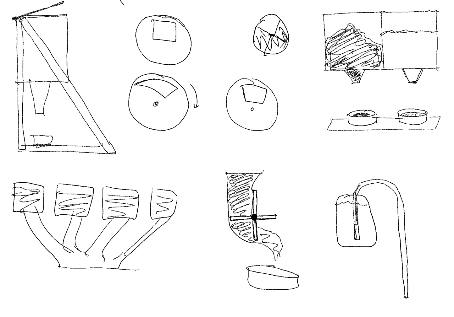
Results
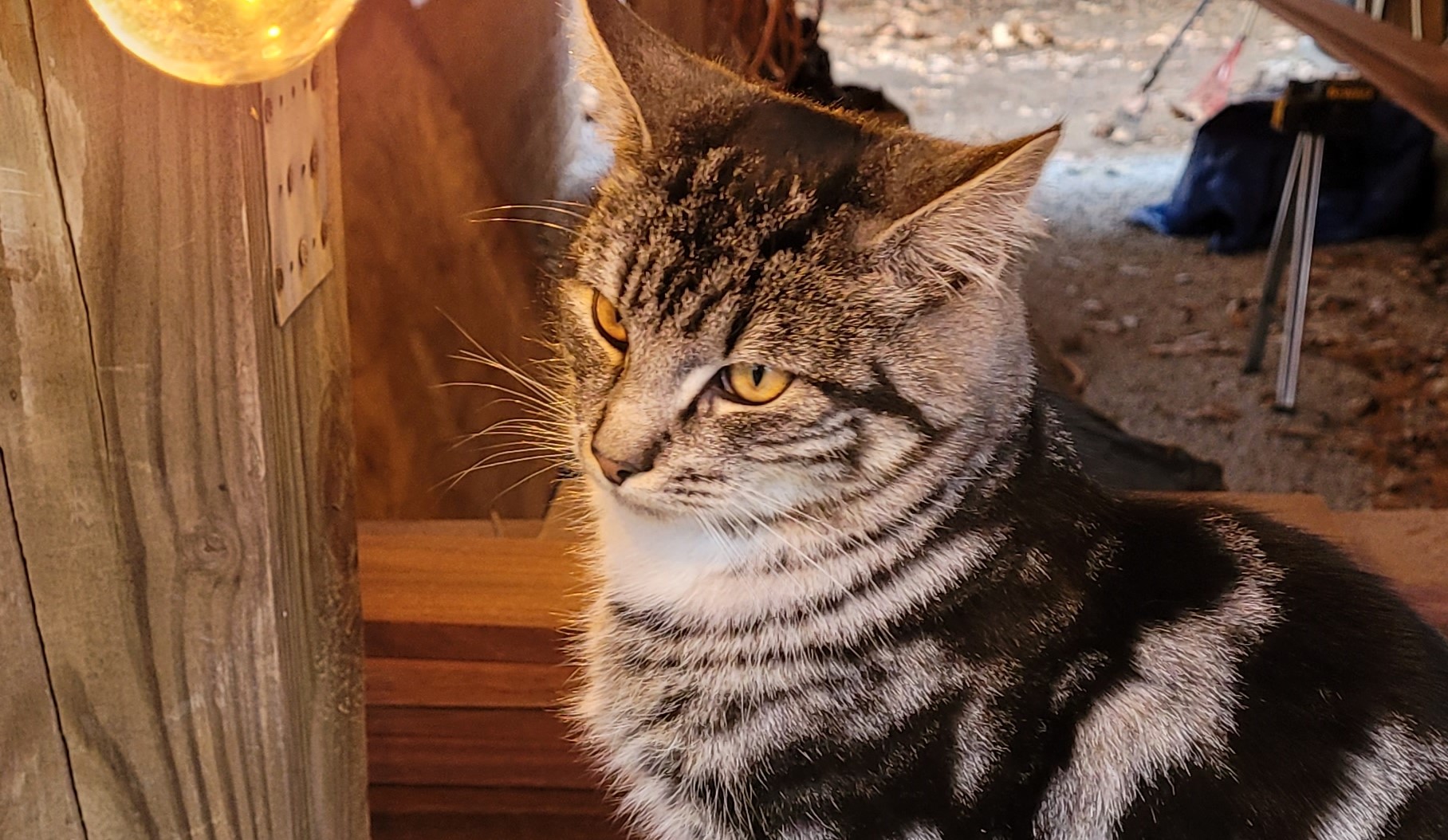
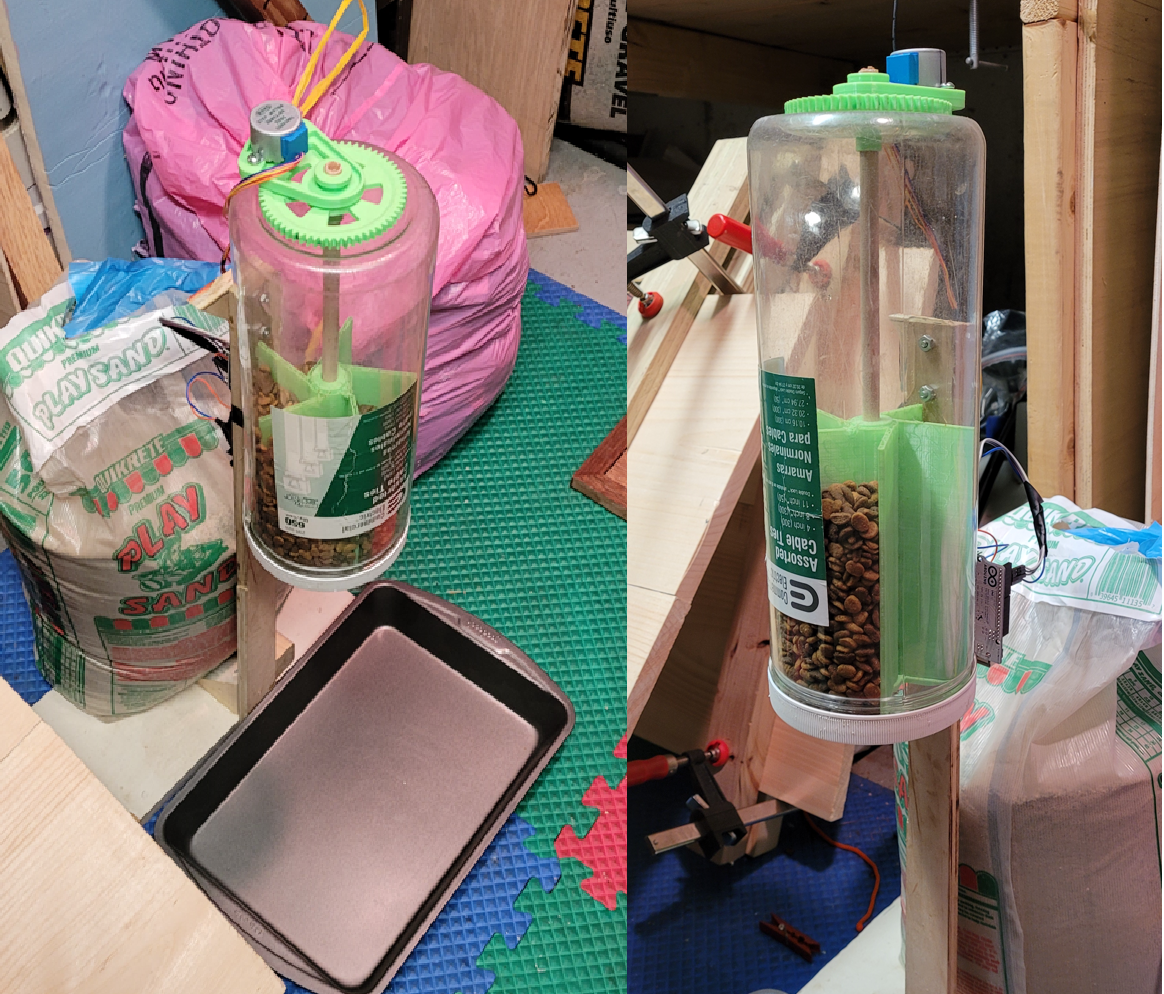
The apparatus successfully dispensed all 5 meals and our cat did not starve to death.
The apparatus successfully dispensed all 5 meals and our cat did not starve to death.
I made a satisfying desk toy.
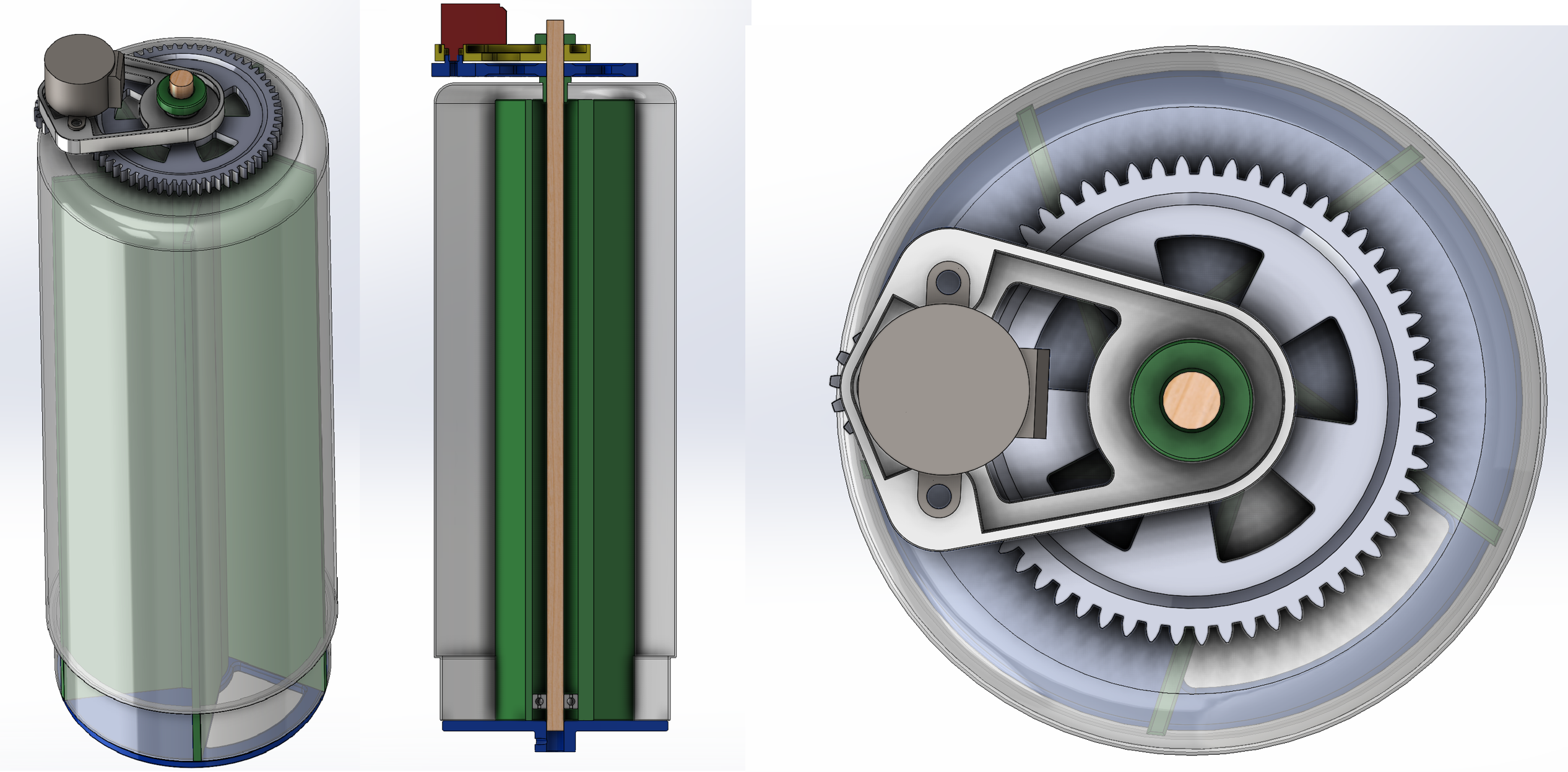
A stainless steel cylinder was fitted into a hollow brass cylinder using thermal press fitting.
Turning was done on a Tormach lathe and the final result was polished.
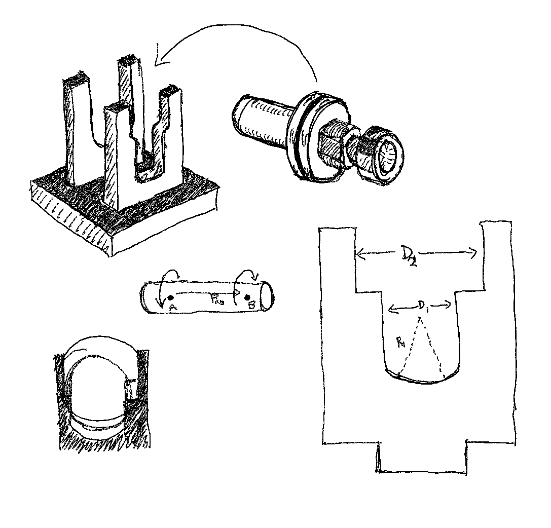
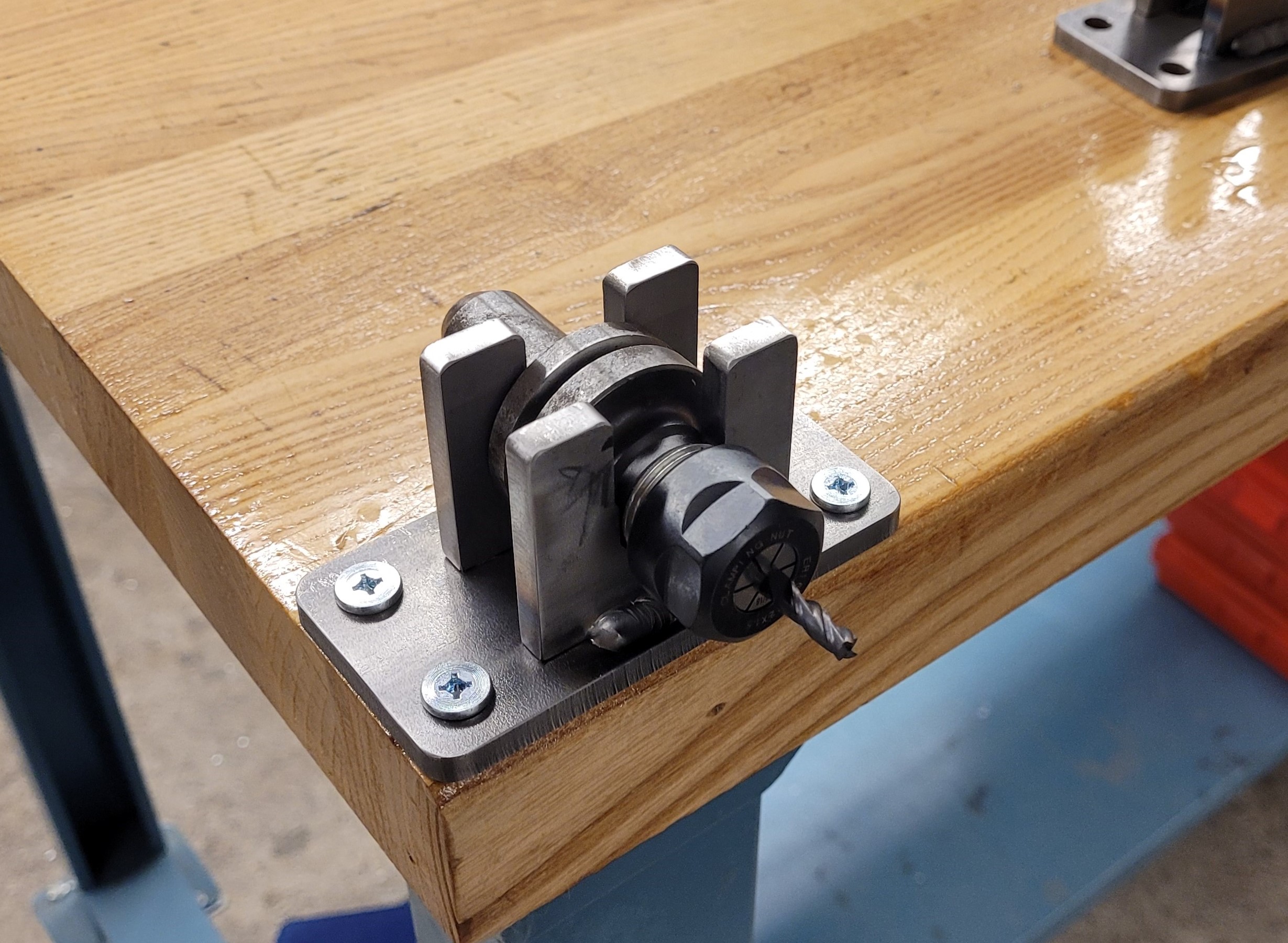
When inserting a cutting tool in a 5C collet (used on the Tormach mills), the collet needs to be secured in place while a torque wrench is used to tighten it properly.
The challenge was to design a toolholder to hold 2 different collet sizes as to economize for space on the worktable.
I also used several components I had on hand which were a Raspberry Pi 2B, and a VEX Mini CIM motor.
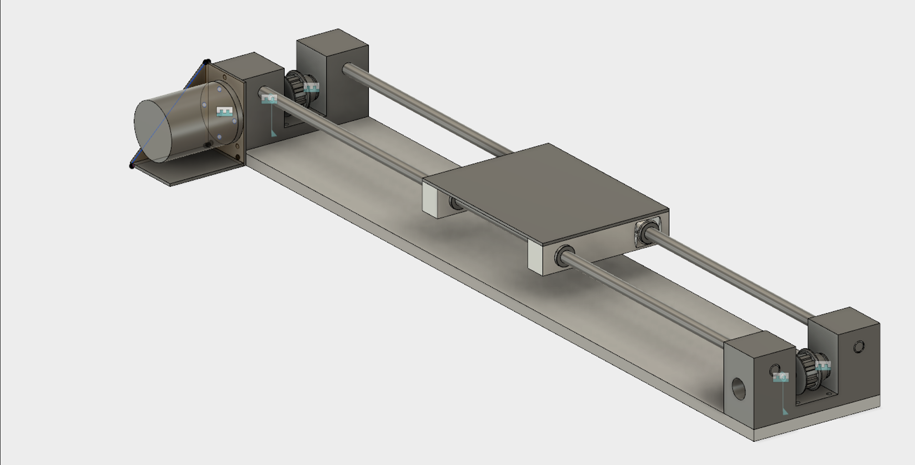
The round linear rails were self-built out of low-cost COTS. The two rails would not need to be adjusted, but instead all the precision would follow from the machined aluminium end blocks.
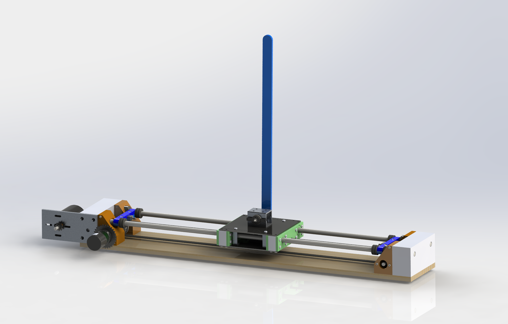
Motor speed reduction would be achieved through a chain-sprocket geartrain at one end.
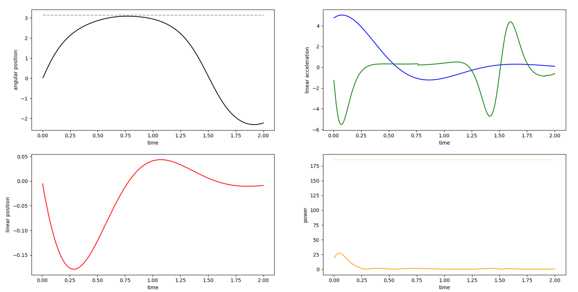
A rotary encoder would measure motor velocity, and another would measure the pendulum tilt angle.
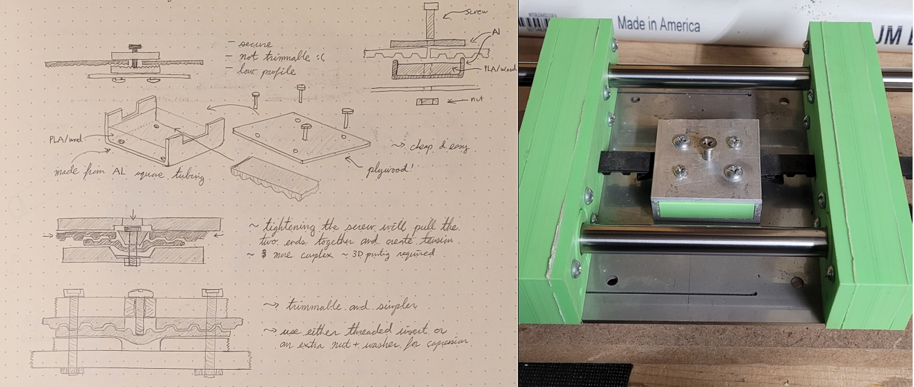
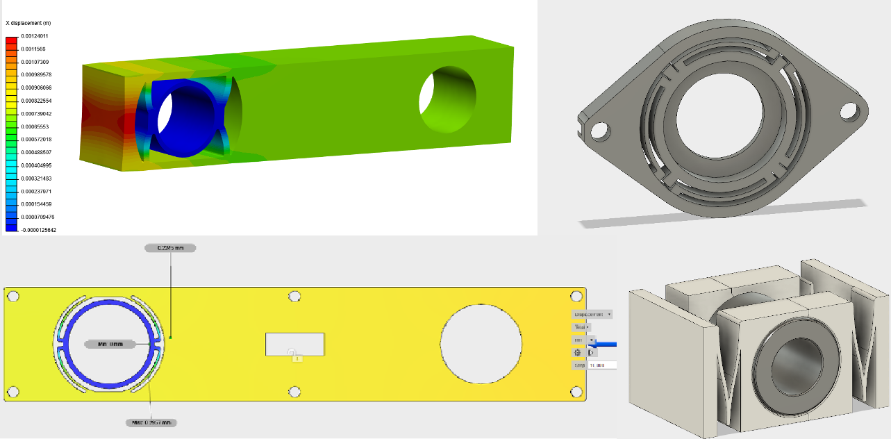
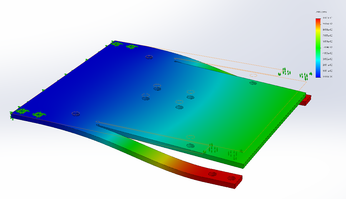
Flexure mechanisms were pursued to reduce tolerance requirements for the linear stage.
One set of mechanical flexures were built into the 3D printed bearing blocks and relieved misalignment in the rail separation.
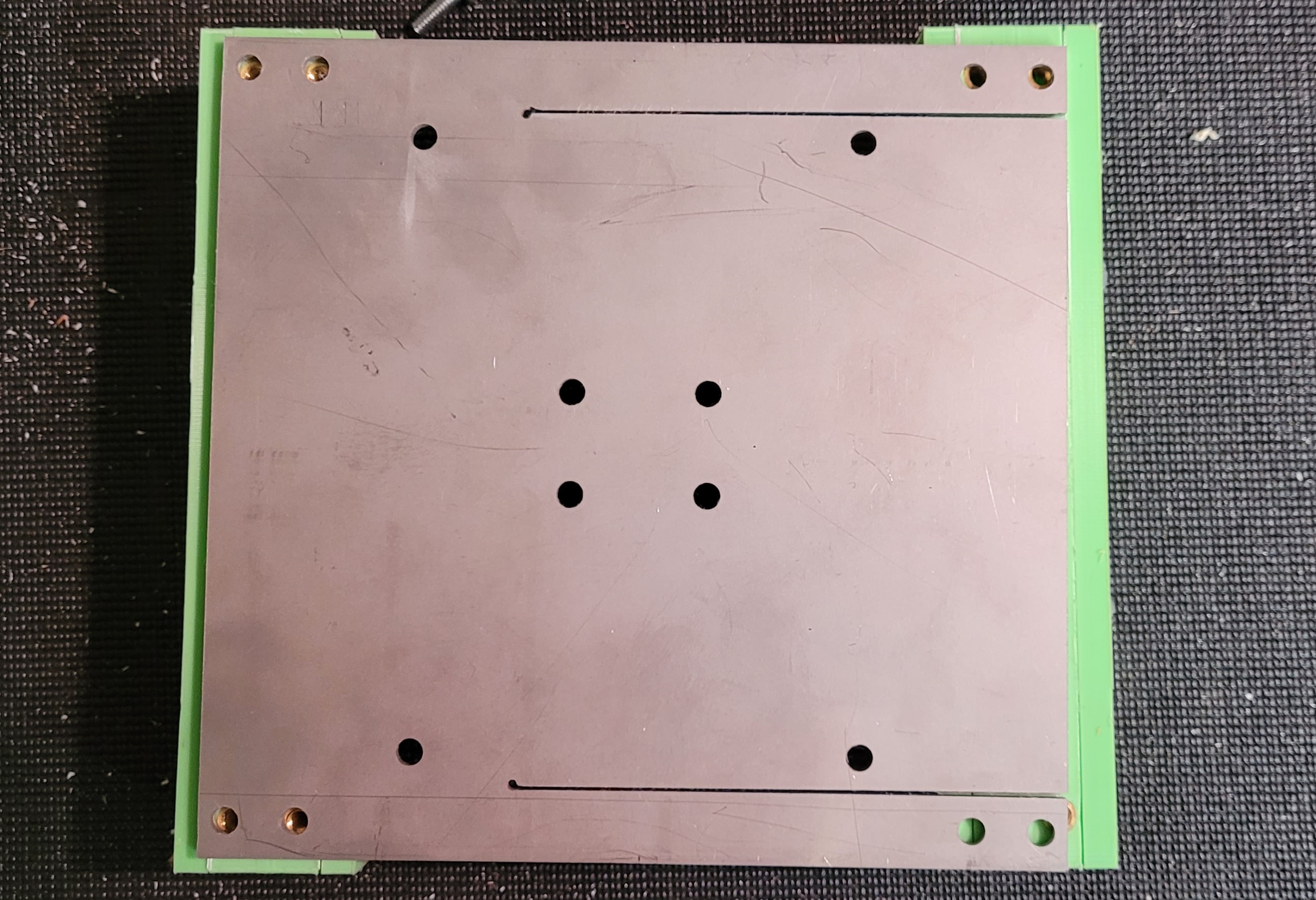
Another set was waterjetted out of the steel carriage plate to take up errors in rail parallelism.
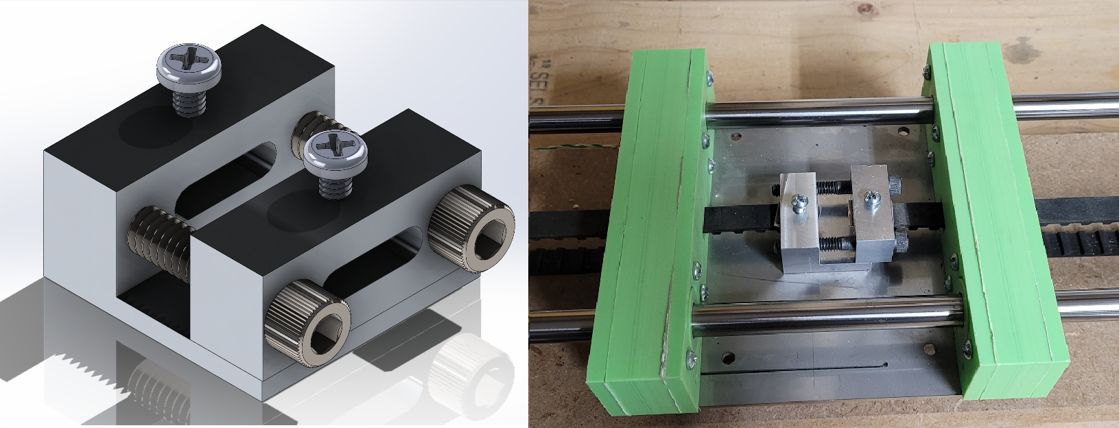
The first iteration for a timing belt tensioner used a separate strip to provide tooth engagement between the two loose ends. A bolt from the top would clamp into a metal plate and onto the top of the connecting piece. This strategy sucked becasue four bolts needed to be tightened at once for maximum force to be applies, plus the tensioning screw tore through the belt multiple times.
A second approach used two clamps mahcined out of aluminium, which would be pulled into each other via two socket head bolts. This approach applied much more tension and took less time to configure, however there was still the issue of securing the belt to either side of the clamp.